Design methods & concepts
The final cover geocomposite is relatively close to the surface of the landfill and is therefore directly affected by short-term inputs from precipitation. The geocomposite is typically overlain by approximately 2 ft (0.6 m) of protective and vegetative soil. The properties of this soil layer can significantly influence how much precipitation impinges on the drainage layer. Thiel and Stewart [1993] describe a relatively simple and conservative method of estimating the amount of liquid that may percolate into the drainage layer. Their approach has since been labeled the “unit gradient” method. The basis for this method is that for the critical condition it can be assumed that the cover soil is saturated, and water from continued rains will percolate vertically through the cover soil. Since the head on top of the cover soil is practically zero (due to runoff), the gradient through the cover soil is unity. The infiltration rate is considered to be equal to the permeability of cover soil (k ). Therefore, Darcy’s law gives the inflow percolation as (see also Figure 4.1):
cover
Q = k × i × A
in
in
cover
EQUATION 4.1
WHERE
Q = inflow percolation rate (m /sec)
k = permeability of cover soil
i = inflow gradient = 1
A = area (m )
3
2
in
in
cover
If we examine a unit width of the cover slope, the area would be equal to the slope length (or distance between drainage outlets), L, times the unit width. Therefore,
Q = k × L
in
cover
EQUATION 4.2
WHERE
Q = inflow percolation rate (m /sec)
k = permeability of cover soil
L = length / distance between drainage outlets
3
in
cover
If we desire that all flow that infiltrates down to the drainage geocomposite is carried entirely by the geocomposite (i.e., the head above the geomembrane is less than or equal to the thickness of the geocomposite), then the limiting flow condition at the downstream end of the geocomposite (per unit width) would be:
Q = k × i × A = k × t × i × 1
out
comp
comp
out
out
Q = θ × sinβ
out req
EQUATION 4.3
WHERE
Q = the flow rate coming out of the drainage geocomposite (m /sec-m)
k = in-plane permeability of the geocomposite
i = the gradient of the flow within geocomposite = sinβ
A = area (m )
t = geotextile thickness (cm)
θ = the transmissivity of the geocomposite (m /sec-m)
β = the slope angle
out
3
comp
out
req
3
2
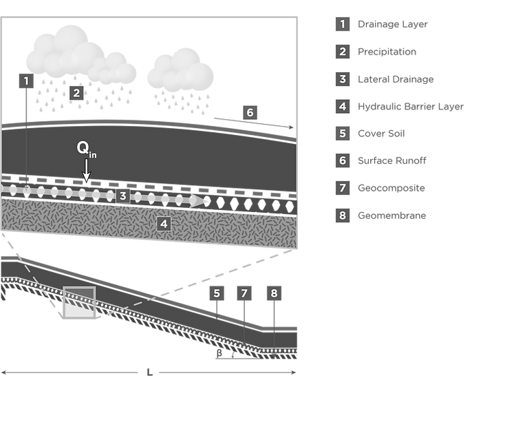
Figure 4.1 disposition of precipitation in a typical final cover system
By establishing that Q = Q , an equation can be written solving for the required transmissivity of the geocomposite, as follows:
in
out
θ =
sinβ
k × L
cover
req
EQUATION 4.4
WHERE
θ = the transmissivity of the geocomposite (m /sec-m)
k = permeability of cover soil
L = length / distance between drainage outlets
β = the slope angle
2
req
cover
Examining Equation 4.4, we see that required transmissivity is a function of the inflow percolation, slope length, and slope angle. A typical underdrain outlet design for a bench location is presented in Figure 4.2.
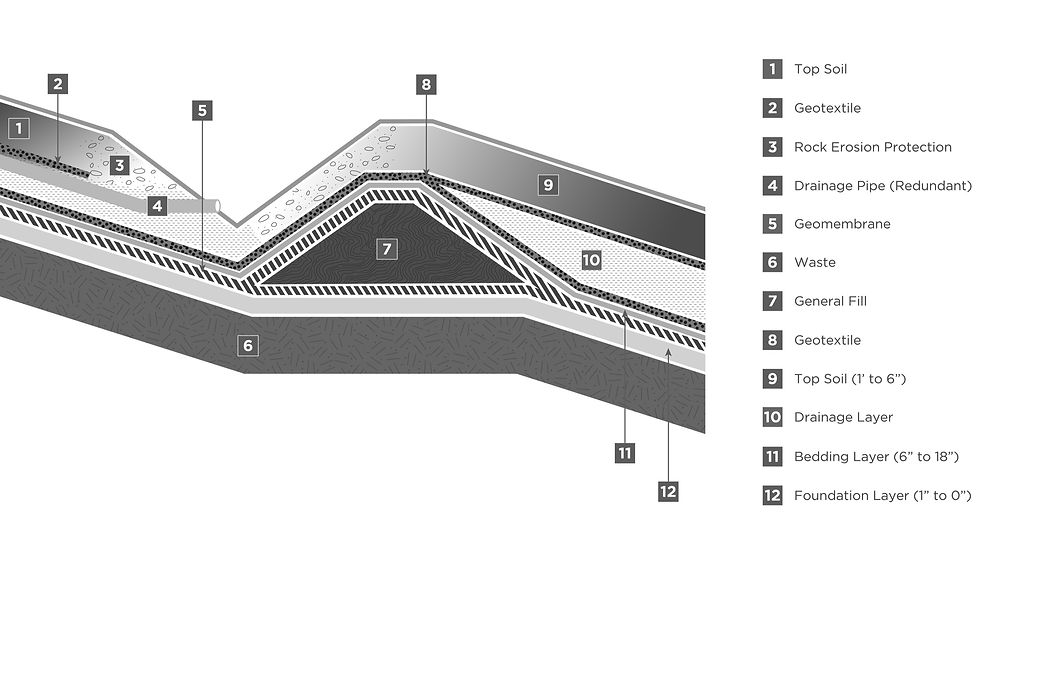
Figure 4.2 typical underdrain outlet at bench
The allowable transmissivity of geocomposite is:
θ = θ × FS
req
allow
EQUATION 4.5
WHERE
allow
req
2
θ = allowable transmissivity of geocomposite
θ = the transmissivity of the geocomposite (m /sec-m)
FS = factor of safety for permeability
The ultimate 100 hour transmissivity test value is calculated as follows:
θ = θ × RF × RF × RF × RF
100 allow in cr cc bc
EQUATION 4.6
TABLE 4.1 – RECOMMENDED REDUCTION FACTOR AND SAFETY FACTOR
RF =
in
RF =
cr
Intrusion Reduction Factor
1.0 - 1.2 ( )
1
RF =
cc
Creep Reduction Factor
Chemical Clogging Reduction Factor
1.0 - 1.2 ( )
2
RF =
bc
Biological Clogging Reduction Factor
1.2 - 3.5 ( )
2
FS =
Overall Factor of Safety
2.0 - 3.0 ( )
3
-
Intrusion reduction factor from 100 hour to design life. Giroud, et. al. (2000)
-
GRI - GC8
-
FS value = 2-3. Giroud, et. al (2000)
Manufacturer Data
LANDFILL FINAL COVER
EQUATION SHEET
Choose input parameter values
L =
meter
Max. horizontal drainage length of slope (or distance between drainage benches/ditches)
β =
degree
Slope angle
k =
cover
cm/sec
Permeability of cover protective soil
γ =
cover
Unit weight of cover protective soil
kN/m³
T =
cover
meter
Thickness of cover protective soil
RF =
in
dimensionless
RF =
cr
Creep Reduction Factor
dimensionless
RF =
cc
Chemical Clogging Reduction Factor
dimensionless
RF =
bc
dimensionless
Biological Clogging Reduction Factor
FS =
dimensionless
Overall Factor of Safety
SOLUTION